Quantcast
Channel: Cisco, Network Equipment Resource
Viewing all 70 articles
Browse latest View live

Cisco Catalyst 2960-X and Catalyst 2960-XR Review

$
0
0
The Catalyst 2960 got stacking via the2960-S model a couple of years ago. It also got the ability to do static routes which was a nice feature. Cisco 2960-X series debut at Cisco Partner Summit 2013. Cisco released the new Catalyst 2960-X series by doubling its stacked port density, stacking bandwidth, buffers and CPU performance. It is the next generation of its wildly successful Catalyst 2K switches. The Cisco 2960-X and -XR are available in 24 or 48 port configurations. Uplinks are either 2x 10 Gbit SPF+ or 4x 1 Gbit SFP. The PoE models can support 370W or 740W of power.

The 2960-X Series provides up to 80 Gbps of stack bandwidth which is 2x more compared to the 2960-S. It is now also possible to stack up to 8 switches compared to the earlier maximum of 4. The 2960-S model uses FlexStack while the newer -X and -XR models uses FlexStack-Plus. FlexStack-Plus supports detecting stack port operational state in hardware and change the forwarding according to it. This takes 100 ms or less. The older model does it in CPU which can take 1 or 2 seconds.

Here are some notable differences between 2960-X and -XR compared to 2960-S.
  • Dual core CPU @ 600 MHz. 2960-S has single core
  • 2960-XR has support for dual power supplies
  • 256 MB of flash for -XR, 128 MB for -X. The S model has 64 MB
  • 512 MB of DRAM compared to 256 for 2960-S
  • 1k active VLANs compared to 255 for 2960-S
  • 48 Etherchannel groups for -XR, 24 for -X and 6 for -S
  • 4 MB of egress buffers instead of 2 MB
  • 4 SPAN sessions instead of 2
  • 32k MACs for -XR, 16k for -X and 8k for -S
  • 24k unicast routes for -XR, 16 static routes for -X and -S
The newer models also support Netflow lite, hibernation mode and EEE. The 2960-XR does support dynamic routing. It has support for RIP, OSPF stub, OSPFv3 stub, EIGRP stub, HSRP, VRRP and PIM.

Here are some performance numbers:
Cisco 2960-X Lan Lite has 100 Gbps of switching bandwidth and 64 active VLANS. The Catalyst 2960-X Lan Base has 216 Gbps of switching bandwidth and 1023 active VLANs. The same holds true for 2960-XR with IP Lite feature set. The 2960-S had a maximum of 255 VLANs and 176 Gbps switching bandwidth. Depending on model the 2960-X tops out at 130.9 Mpps compared to 101.2 for 2960-S.

The switches also have added support for IPv6. Notable features are:
  • IPv6 MLDv1 and v2 snooping
  • IPv6 First Hop Security (RA guard, source guard, and binding integrity guard
  • IPv6 ACLs
  • IPv6 QoS
  • HTTP/HTTPs over IPv6
  • SNMP over IPv6
  • Syslog over IPv6
More Reviews Related to Cisco Catalyst 2960-X Series:

Tips for Power Supply for Cisco 3750-X and Catalyst 3560-X Switch

$
0
0
The CiscoCatalyst3750-X and 3560-X Series Switches are an enterprise-class lines of stackable and standalone switches, respectively. These switches provide high availability, scalability, security, energy efficiency, and ease of operation with innovative features such as Cisco StackPower (available only on the Catalyst 3750-X), IEEE 802.3at Power over Ethernet Plus (PoE+) configurations, optional network modules, redundant power supplies, and Media Access Control Security (MACsec) features. 

Combining 10/100/1000 and Power over Ethernet Plus (PoE+) or GE SFP configurations with four optional uplinks, the Cisco Catalyst 3750-X and 3560-X Series Switches enhance worker productivity by enabling applications such as encryption, IP telephony, wireless, and video.

The Cisco Catalyst 3750-X and 3560-X Series Switches are built on the existing Cisco Catalyst 3750-E and 3560-E Series Switches, using the same port application-specific integrated circuit (ASIC), switch fabric, and Cisco IOSSoftware feature sets.

About Power Supply for Cisco Catalyst 3750-X & 3560-X Series Switches, you know that the Catalyst 3750-X Series and Cisco 3560-X Series Switches support dual redundant power supplies. The switch ships with one power supply by default and the second power supply can be purchased at the time of ordering the switch or at a later time. If only one power supply is installed, it should always be in the power supply bay 1. 


Table shows the different power supplies available in these switches and available PoE power.
Power Supply Models
Models
Default Power Supply
Available PoE Power
24 Port Data Switch
C3KX-PWR-350WAC
-
48 Port Data Switch
24 Port PoE Switch
435W
48 Port PoE Switch
48 Port Full PoE Switch
800W

More Related Cisco 3750 and Catalyst 3560 Switch Tips:

List of Featured Cisco Access Points for Enterprises

$
0
0

Cisco Access Points---simplify your working environment by combining the mobility of wireless with the performance of wired networks.


      • Includes automatic interference mitigation for 802.11n performance protection
      • Helps enable remote troubleshooting for fast diagnostics and less downtime
      • Detects off-channel rogues using first access point with non-Wi-Fi detection
      • Enforces policy with intelligent identification of wireless devices


      • Extends flexibility with rugged, indoor, non-modular 802.11n access points
      • Uses current antenna portfolio in lightweight form factor
      • Allows quick installation on Cisco 1130/1240 mounting brackets

 Cisco 5500 Series Wireless LAN Controller


      • Integrates next generation wireless into highly scalable platform
      • Allows connection of up to 500 access points
      • Supports ClientLink, VideoStream, CleanAir Technology, and OfficeExtend

Wireless Control System
      • Reduces operational costs with built-in tools, guides, and templates
      • Improves IT efficiency through intuitive GUI and flexible ease of use
      • Minimizes IT staffing requirements through centralized operational control
      • Scales to small, midsize, and large-scale wireless LANs across all locations 

Cisco 3300 Series Mobility Services Engine
      • Simplifies provisioning and management of mobility services
      • Offers scalable and reliable multidevice, multinetwork application delivery
      • Facilitates broad partner ecosystem for mobile applications development
      • Locates interferer devices and determines impact zone
 
Notes:Wireless access is a great choice for easy, convenient internet and network access from anywhere you need it. And different products can allow you to extend the wireless range to just your apartment, your office building, or your entire campus.

More Cisco Access Point Topics:

CISCO CP7937G, Better Sound, Simpler Management

$
0
0


CiscoUnified IP phones provide exceptional levels of integrated business functionality and converged communications features, surpassing today's conventional voice systems and competitive offerings. As the market leader in IP telephony, Cisco continues to deliver comprehensive end-to-end data and true voice-over-IP (VoIP) solutions, offering a complete, stylish and fully featured IP phone portfolio for enterprise and small- and midsized-business (SMB) customers.

The Cisco Unified IP Conference Station 7937G combines state-of-the-art wideband speakerphone conferencing technologies with award-winning Cisco voice communication technologies. The net result is a conference room phone that offers superior wideband voice and microphone quality, with simplified wiring and administrative cost benefits. A full-featured, IP-based, hands-free conference station, the new Cisco Unified IP Conference Station 7937G is designed for use on desktops, in conference rooms, and in executive suites.

NOTE: More about Cisco Unified Communications Solutions
CiscoUnified Communications Solutions unify voice, video, data, and mobile applications on fixed and mobile networks, delivering a media-rich collaboration experience across business, government agency, and institutional workspaces. These applications use the network as the platform to enhance comparative advantage by accelerating decision time and reducing transaction time. The security, resilience, and scalability of the network enable users in any workspace to easily connect anywhere, anytime, and anyplace, using any media, device, or operating system. Cisco Unified Communications is part of a comprehensive solution that includes network infrastructure, security, wireless, management applications, lifecycle services, flexible deployment and outsourced management options, and third-party applications.

The Cisco Unified IP Conference Station 7937G offers many new features, including:
• Superior wideband acoustics with the support of the G.722 wideband codec
• Support for IEEE Power over Ethernet (PoE) or the Cisco Power Cube 3
• Expanded room coverage up to 30 feet by 40 feet with the optional external microphone kit
• Support for a third-party lapel microphone kit
• New larger backlit liquid crystal display (LCD)
• Global localization within six months of first customer shipment (FCS)

Cisco Unified IP Conference Station 7937G


FULL OVERVIEW TO KNOW Cisco CP-7937G
Cisco Unified IP Conference Station 7937—Components and Connections

1
Power outlet in the wall
6
RJ-45 port on the bottom of the Cisco Unified IP Conference Station
2
Power supply
7
Free end of the 25-foot CAT 5 cable
3
Power supply power cord
8
LAN connection on PIM
4
PIM
9
25-foot CAT 5 cable connection on PIM
5
LAN connection
10
DC adapter port on PIM for power supply unit

External Microphone Connections on the Cisco Unified IP Conference Station 7937

1
Connect one end of the external microphone cable to the jack on the underside of the external microphone.
2
Connect the other end of the external microphone cable to the external microphone jack on the underside of the Cisco Unified IP Conference Station 7936.

How to Install a Cisco Unified IP Conference Station? Simple steps as follows:
Step1. Place the Cisco Unified IP Conference Station on a flat surface, for example, a conference room table or desktop.
Step2. Connect one end of the 6-foot CAT 5 cable to your data network port and connect the other end to the network (LAN) port on the PIM.
Step3. Connect the free end of the 25-foot CAT 5 cable to the RJ-45 port on the bottom of the Cisco Unified IP Conference Station. (The cable is pre-plugged into the PIM.)
Step4. Connect the power supply unit to the AC adapter port on the PIM, and plug the other end into a standard electrical power outlet in the wall.
Step5. If you are using the External Microphone Kit, connect each of the microphone extensions to the microphone jacks installed on the underside of the Cisco Unified IP Phone 7936. See Figure of External Microphone Connections on the Cisco Unified IP Conference Station 7936for an illustration of this connection.

Note: If you do not correctly connect the cables, PIM, and the power supply, the Cisco Unified IP Conference Station will not work. 
Use of any device other than the Cisco-provided external microphone kit will not work and may void the Cisco Unified IP Conference Station product warranty.

Note: More info of Installing the Cisco Unified IP Conference Station 7936 (Preparing to Install, Setting the Default Device Load, Adding a New Device, Using Auto-Registration, Adding Cisco Unified IP Conference Stations Manually, etc.) you can visit:
http://www.cisco.com/en/US/docs/voice_ip_comm/cuipph/7936/5_0/english/administration/guide/7936ins.html#wp1017889

More Related Cisco CP-7937G-Cisco Unified IP Conference Station 7937G Features and Benefits, Detailed Features, Specifications, AC Country Power Cords, Ordering Information, etc. you can see at
http://www.cisco.com/en/US/prod/collateral/voicesw/ps6788/phones/ps379/ps8759/product_data_sheet0900aecd806e021a.html

Q and A: Cisco Unified IP Phone 7900 Series
http://www.cisco.com/en/US/products/hw/phones/ps379/prod_qandas_list.html

More Cisco IP Phone Topics:

WLC Configuration to Different Regions Aps

$
0
0


Cisco 2500 Series Wireless Controller support a maximum of 50 lightweight APs in increments of 5 APs with a minimum of 5 APs, making it a cost-effective solution for retail and small and medium-sized businesses. The Cisco 2500 Series Wireless Controller offers robust coverage with 802.11a/b/g or delivers unprecedented reliability using 802.11n and Cisco Next-Generation Wireless Solutions and Cisco Enterprise Wireless Mesh.

Here I would like to share my experience of WLC Configuration to Different Aps Regions.
I have a Cisco 2504 WLC running Software Version 7.4.110.0 and I have 3 AIR-CAP1602I-C-K9ssetup on it. Here I also checked the AP image to WLC 2504 and have log as follows:
Primary AP     Image Size
----------------             ----
ap1g2                   9568
ap3g1                   11288
ap3g2                   11196
ap801                   7164
ap802                   8568
c1130                   5072
c1140                   9416
c1250                   6944
c1520                   8044
c602i                   3736
 Secondary AP     ImageSize
------------------            ----
ap3g1                   5792
ap801                   5192
ap802                   5232
c1100                   3084
c1130                   4964
c1140                   4992
c1200                   3364
c1240                   4812
c1250                   5504
c1310                   3136
c1520                   6404
c3201                   4324
c602i                   3716

I got that the c602i is the AP image I need for my APs. But the problem is the WLC cannot find the APs, so I read Log from AP details below:
13 12:44:26.607: %CAPWAP-3-ERRORLOG: Retransmission count for packet exceeded max(UNKNOWN_MESSAGE_TYPE (5)
*Nov 13 12:44:26.607: %CAPWAP-3-ERRORLOG: GOING BACK TO DISCOVER MODE
*Nov 13 12:44:26.607: %DTLS-5-SEND_ALERT: Send FATAL : Close notify Alert to 192.168.1.30:5246
*Nov 13 12:44:26.651: %LWAPP-3-CLIENTERRORLOG: LWAPP LED Init: incorrect led state 255
*Nov 13 12:44:26.671: %LINK-5-CHANGED: Interface Dot11Radio0, changed state to administratively down
*Nov 13 12:44:26.671: %LINK-5-CHANGED: Interface Dot11Radio1, changed state to administratively down
*Nov 13 12:44:26.687: %LINK-6-UPDOWN: Interface Dot11Radio0, changed state to up
*Nov 13 12:44:26.719: %LINK-6-UPDOWN: Interface Dot11Radio1, changed state to up
*Nov 13 12:44:27.667: %LINEPROTO-5-UPDOWN: Line protocol on Interface Dot11Radio0, changed state to down
*Nov 13 12:44:27.719: %LINK-6-UPDOWN: Interface Dot11Radio1, changed state to down
*Nov 13 12:44:27.727: %LINK-5-CHANGED: Interface Dot11Radio1, changed state to reset
*Nov 13 12:44:28.711: %LINEPROTO-5-UPDOWN: Line protocol on Interface Dot11Radio0, changed state to up
*Nov 13 12:44:28.719: %LINEPROTO-5-UPDOWN: Line protocol on Interface Dot11Radio1, changed state to down
*Nov 13 12:44:28.763: %LINK-6-UPDOWN: Interface Dot11Radio1, changed state to up
*Nov 13 12:44:28.771: %LINK-6-UPDOWN: Interface Dot11Radio0, changed state to down
*Nov 13 12:44:28.779: %LINK-5-CHANGED: Interface Dot11Radio0, changed state to reset
*Nov 13 12:44:29.763: %LINEPROTO-5-UPDOWN: Line protocol on Interface Dot11Radio1, changed state to up
*Nov 13 12:44:29.771: %LINEPROTO-5-UPDOWN: Line protocol on Interface Dot11Radio0, changed state to down
*Nov 13 12:44:29.807: %LINK-6-UPDOWN: Interface Dot11Radio0, changed state to up
*Nov 13 12:44:30.807: %LINEPROTO-5-UPDOWN: Line protocol on Interface Dot11Radio0, changed state to up
*Nov 13 12:44:42.719: %CAPWAP-3-ERRORLOG: Go join a capwap controller
*Nov 13 12:44:42.000: %CAPWAP-5-DTLSREQSEND: DTLS connection request sent peer_ip: 192.168.1.30 peer_port: 5246
*Nov 13 12:44:42.507: %CAPWAP-5-DTLSREQSUCC: DTLS connection created sucessfully peer_ip: 192.168.1.30 peer_port: 5246
*Nov 13 12:44:42.507: %CAPWAP-5-SENDJOIN: sending Join Request to 192.168.1.30
*Nov 13 12:44:42.511: %CAPWAP-3-ERRORLOG: Invalid event 10 & state 5 combination.
*Nov 13 12:44:42.511: %CAPWAP-3-ERRORLOG: CAPWAP SM handler: Failed to process message type 10 state 5.
*Nov 13 12:44:42.511: %CAPWAP-3-ERRORLOG: Failed to handle capwap control message from controller
*Nov 13 12:44:42.511: %CAPWAP-3-ERRORLOG: Failed to process encrypted capwap packet from 192.168.1.30

In fact, it took me much time to solve this problem, I finally realized that Cisco has configured a country code ensures that each radio’s broadcast frequency bands, interfaces, channels and transmit power levels are compliant with country-specific regulations. Well, I changed the country code of my WLC and last it worked.

How to change the country code of a WLC? Before you can change the country code of a WLC, you must disable the 802.11a and 802.11b network:
>config 802.11a disable network
>config 802.11b disable network

Now you can change the country code of the controller. For example, we change it from US to CN (CHINA)
>config country CN
After changing the country, enable the 802.11 interfaces.
>config 802.11a enable network
>config 802.11b enable network
Change the Timezone if necessary on WLC:
(Cisco Controller) >config time timezone 2 0
And now we’ve got the right time :
(Cisco Controller) >show time
Time……………………………………… Thu Nov 17 16:50:17 2013
Change time on AP:
clock set hh:mm:ssday month year

More Cisco Networking Guide and Tips:

Cisco Catalyst 3750-X and 3560-X StackPower Overview

$
0
0
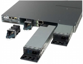
StackPower creates a power backplane among the switches in your stack, allows the power supplies to supply power to any switch in the stack. This means that you no longer have to have redundant power supplies in every switch. For example, in a switch stack that’s two units high, you could order a total of three power supplies. One per switch to provide enough power budget, and then a third that would act conceptually as a floating spare, filling in if either of the other two experienced a failure.

Another benefit is that you can replace a power supply in a switch without ever having to take the switch offline; assuming you’ve got the spare power budget available, StackPower will take care of keeping your switch powered while you replace the defective supply, even if that was the only supply in that physical switch.


Using StackPower
Note that StackPower is not supported in the LAN Base image. You need IP Base image or higher.
By default, StackPower comes up in power sharing mode, as opposed to redundant mode. That means that all power supplies detected in the switches are treated as one gigantic power supply.  If there is a power supply, the switch stack might have to shed some power (i.e. shut something down) so that the system conforms to the new, lower power budget created by the failed supply.

Take a look. First, I do a boring old “show env power all” to get a look at all the power supplies known to the stack, which in this case is a pair of 350W supplies in each switch. Then we look at the default state of the stack-power, having not done any configuration as yet. Note that I have both StackPower cables connected from switch 1 to switch 2.


Switch#show env power all
 SW  PID                 Serial#     Status           Sys Pwr  PoE Pwr  Watts
---  ------------------  ----------  ---------------  -------  -------  -----
1A  C3KX-PWR-350WAC     DTN1526L0PJ OK              Good     Good     350/0
1B  C3KX-PWR-350WAC     DTN1526L0PK OK              Good     Good     350/0
2A  C3KX-PWR-350WAC     DTN1526L0NV OK              Good     Good     350/0
2B  C3KX-PWR-350WAC     DTN1526L0NW OK              Good     Good     350/0

Switch#show stack-power
Power stack name: Powerstack-1
    Stack mode: Power sharing strict
    Stack topology: Ring
    Switch 1:
        Power budget: 223
        Low port priority value: 21
        High port priority value: 12
        Switch priority value: 3
        Port 1 status: Connected
        Port 2 status: Connected
        Neighbor on port 1: 7081.0588.9380
        Neighbor on port 2: 7081.0588.9380

    Switch 2:
        Power budget: 223
        Low port priority value: 22
        High port priority value: 13
        Switch priority value: 4
        Port 1 status: Connected
        Port 2 status: Connected
        Neighbor on port 1: 7081.0567.7b00
        Neighbor on port 2: 7081.0567.7b00
Switch#

You can choose between power-sharing (one big happy power supply) and redundant (the largest power supply is kept as a reserve). Also, each of these support modes of strict & non-strict.

“In strict mode, when a power supply fails and the available power drops below the budgeted power, the system balances the budget through load shedding of powered devices, even if the actual power being consumed is less than the available power.” In other words, no chances are taken that devices could exceed budget.

“In non-strict mode, the power stack is allowed to run in an over-allocated state and is stable as long as the actual power does not exceed the available power. In this mode, a powered device drawing more than normal power could cause the power stack to start shedding loads. This is normally not a problem because most devices do not run at full power and the chances of multiple powered devices in the stack requiring maximum power at the same time is small.” Here, Cisco will let you roll the dice under the assumption that it’s unlikely everyone in the stack is going to need max power. So technically, it’s possible to exceed power budget in this configuration, but the hope is that it won’t happen.

Seen from the output above, the default mode is “power sharing strict”. Now, you might not want power sharing mode. Your alternative is redundant mode, which is easy enough to set.
Switch#conf t
Enter configuration commands, one per line.  End with CNTL/Z.
Switch(config)#stack-power stack ?
  WORD  Power stack name - Up to 31 chars

Switch(config)#stack-power stack Powerstack-1
Switch(config-stackpower)#?
Power stack configuration mode:
  default  Set a command to its defaults
  exit     Exit from power stack configuration
  mode     Power stack mode
  no       Negate a command or set its defaults

Switch(config-stackpower)#mode ?
  power-shared  Power shared mode
  redundant     Redundant mode

Switch(config-stackpower)#mode redundant ?
  strict  Strict mode
  <cr>

Switch(config-stackpower)#mode redundant strict
Switch(config-stackpower)#^Z
Switch#show stack-power
Power stack name: Powerstack-1
    Stack mode: Redundant strict
    Stack topology: Ring
    Switch 1:
        Power budget: 223
        Low port priority value: 21
        High port priority value: 12
        Switch priority value: 3
        Port 1 status: Connected
        Port 2 status: Connected
        Neighbor on port 1: 7081.0588.9380
        Neighbor on port 2: 7081.0588.9380

    Switch 2:
        Power budget: 223
        Low port priority value: 22
        High port priority value: 13
        Switch priority value: 4
        Port 1 status: Connected
        Port 2 status: Connected
        Neighbor on port 1: 7081.0567.7b00
        Neighbor on port 2: 7081.0567.7b00

Switch#

You can also configure the load-shedding order (what ports and/or switches get power removed first). This could be useful in a PoE scenario where you want certain wireless access points or IP phones to lose power before others ones so as to minimize the impact to your company during a power supply failure.

So what’s a power supply failure look like? With my stack-power configured in “redundant strict” mode (meaning one supply is a spare, and potential power requirement cannot exceed power budget), I am going to disconnect one of the supplies on the switch I am consoled into, which happens to be switch 1 in the stack, as well as the master switch.
Switch#
*Mar  1 01:53:20.862: %PLATFORM_ENV-1-FRU_PS_ACCESS: FRU Power Supply is not responding
*Mar  1 01:53:21.843: %PLATFORM_STACKPOWER-4-REDUNDANCY_LOSS: Switch 1's power stack lost redundancy and is now operating in power sharing mode
*Mar  1 01:53:23.831: %PLATFORM_ENV-1-FRU_PS_SIGNAL_FAULTY: POWER_GOOD signal on power supply 2 is faulty
Switch#
*Mar  1 01:54:08.627: %PLATFORM_STACKPOWER-4-REDUNDANCY_LOSS: Switch 1's power stack lost redundancy and is now operating in power sharing mode
*Mar  1 01:55:08.630: %PLATFORM_STACKPOWER-4-REDUNDANCY_LOSS: Switch 1's power stack lost redundancy and is now operating in power sharing mode
*Mar  1 01:56:08.634: %PLATFORM_STACKPOWER-4-REDUNDANCY_LOSS: Switch 1's power stack lost redundancy and is now operating in power sharing mode
*Mar  1 01:57:08.638: %PLATFORM_STACKPOWER-4-REDUNDANCY_LOSS: Switch 1's po

The switch logs several messages. First, the power supply is seen as no longer responded. Second, the loss of redundancy is noted (hey, we’re not redundant anymore, so I guess we’re in power sharing mode). Third, the specific power supply with the fault is noted. Last, the lost redundancy state is repeated every 60 seconds.

Now I’m going to disconnect the second power supply on switch 1. If there enough power budget (these are not PoE switches), there should be enough power budget to continue on.
Switch#
*Mar  1 01:57:53.844: %PLATFORM_STACKPOWER-4-UNBALANCED_PS: Switch 1's power stack has unbalanced power supplies
*Mar  1 01:57:55.857: %PLATFORM_ENV-1-FRU_PS_SIGNAL_FAULTY: POWER_GOOD signal on power supply 1 is faulty
*Mar  1 01:58:08.641: %PLATFORM_STACKPOWER-4-REDUNDANCY_LOSS: Switch 1's power stack lost redundancy and is now operating in power sharing mode
Switch#show stack-power
Power stack name: Powerstack-1
    Stack mode: Redundant strict
    Stack topology: Ring
    Switch 1:
        Power budget: 223
        Low port priority value: 21
        High port priority value: 12
        Switch priority value: 3
        Port 1 status: Connected
        Port 2 status: Connected
        Neighbor on port 1: 7081.0588.9380
        Neighbor on port 2: 7081.0588.9380

    Switch 2:
        Power budget: 223
        Low port priority value: 22
        High port priority value: 13
        Switch priority value: 4
        Port 1 status: Connected
        Port 2 status: Connected
        Neighbor on port 1: 7081.0567.7b00
        Neighbor on port 2: 7081.0567.7b00

*Mar  1 01:58:37.825: %PLATFORM_STACKPOWER-4-UNBALANCED_PS: Switch 2's power stack has unbalanced power supplies
Switch#show env power all
 SW  PID                 Serial#     Status           Sys Pwr  PoE Pwr  Watts
---  ------------------  ----------  ---------------  -------  -------  -----
1A  C3KX-PWR-350WAC     DTN1526L0PJ No Input Power  Bad      N/A      350/0
1B  C3KX-PWR-350WAC     DTN1526L0PK No Input Power  Bad      N/A      350/0
2A  C3KX-PWR-350WAC     DTN1526L0NV OK              Good     Good     350/0
2B  C3KX-PWR-350WAC     DTN1526L0NW OK              Good     Good     350/0

Switch#
*Mar  1 01:59:08.645: %PLATFORM_STACKPOWER-4-UNBALANCED_PS: Switch 1's power stack has unbalanced power supplies
*Mar  1 01:59:08.645: %PLATFORM_STACKPOWER-4-REDUNDANCY_LOSS: Switch 1's power stack lost redundancy and is now operating in power sharing mode
*Mar  1 02:00:08.649: %PLATFORM_STACKPOWER-4-UNBALANCED_PS: Switch 1's power stack has unbalanced power supplies
*Mar  1 02:00:08.649: %PLATFORM_STACKPOWER-4-REDUNDANCY_LOSS: Switch 1's po

So at this point, the two power supplies in switch 1 are disconnected, and the two supplies in switch 2 are still up. Now there’s a pair of messages being logged every minute, complaining about the loss of redundancy, and the loss of balanced power.

Let’s go for the gold. What happens when we disconnect one of the two remaining power supplies? Amazingly, a single 350W supply seems to be enough to keep these two 3750X’s running, although admittedly there are no 10GBE optical modules installed. Still, impressive.
Switch#
*Mar  1 02:03:21.058: %PLATFORM_STACKPOWER-4-UNDER_BUDGET: Switch 2 does not have sufficient power budget
*Mar  1 02:03:20.052: %PLATFORM_ENV-1-FRU_PS_ACCESS: FRU Power Supply is not responding (Switch-2)
*Mar  1 02:03:22.040: %PLATFORM_ENV-1-FRU_PS_SIGNAL_FAULTY: POWER_GOOD signal on power supply 1 is faulty (Switch-2)
Switch#
Switch#show switch
Switch/Stack Mac Address : 7081.0567.7b00
                                           H/W   Current
Switch#  Role   Mac Address     Priority Version  State
----------------------------------------------------------
*1       Master 7081.0567.7b00     1      1       Ready
 2       Member 7081.0588.9380     1      1       Ready

Switch#show env power all
 SW  PID                 Serial#     Status           Sys Pwr  PoE Pwr  Watts
---  ------------------  ----------  ---------------  -------  -------  -----
1A  C3KX-PWR-350WAC     DTN1526L0PJ No Input Power  Bad      N/A      350/0
1B  C3KX-PWR-350WAC     DTN1526L0PK No Input Power  Bad      N/A      350/0
2A  C3KX-PWR-350WAC     DTN1526L0NV No Input Power  Bad      N/A      350/0
2B  C3KX-PWR-350WAC     DTN1526L0NW OK              Good     Good     350/0

Switch#

The way power is shared here makes a 3750-X behave like a chassis.

More Cisco StackPower Reviews:

Cisco Catalyst 4948E Ethernet Switch for High-Performance Data Center Accesss

$
0
0


Cisco Catalyst 4900 Series Switches deliver high-performance, low-latency wire-speed Layer 2 and 3 services in a small form factor (1 or 2 rack units). The 4900 Series is ideal for space-constrained deployments.

The Cisco Catalyst4948E offers forty-eight 10/100/1000-Gbps RJ45 downlink ports and four 1/10 Gigabit Ethernet uplink ports and is designed to simplify data center architecture and operations by offering enterprise-class hardware and software in a one-rack-unit (1RU) form factor optimized for smart top-of-rack (ToR) data center deployments.


New Features of Cisco Catalyst 4948ESwitch
The Cisco Catalyst 4948E offers:
• Twice the uplink capacity of the previous switch generation
• 1+1 power supply and fan redundancy for hardware replacement with no downtime
• Strict front-to-back cooling with no side or top venting
• Large shared packet buffers for microburst protection
• Nonblocking internal packet switching for east-to-west traffic patterns
• Full set of Layer 2 and 3 forwarding features
• Outstanding multicast performance
• Zero-touch provisioning with Cisco IOS Embedded Event Manager (EEM)
• Advanced quality of service (QoS)
• IP Version 6 (IPv6) switching and routing in hardware
• Extended MAC address tables to enable server virtualization

Table 1 summarizes the main features of the Cisco Catalyst 4900 Series Switches.
Table1. Cisco Catalyst 4900 Series Features
Feature
Cisco Catalyst 4948 Switch
Cisco Catalyst 4948 10 Gigabit Ethernet Switch
Cisco Catalyst 4948E Switch
Performance

Switching capacity
96 Gbps
136 Gbps
176 Gbps
Throughput
72 million packets per second (mpps)
102 mpps
131-mpps IPv4 switching
110-mpps IPv6 switching
CPU
266 MHz
666 MHz
1.0 GHz
Synchronous Dynamic RAM (SDRAM)
256 MB
256 MB
1024 MB
Active VLANs
4096
4096
4096
Multicast entries
• 28,000 (Layer 3)
• 16,000 (Layer 2)
• 28,000 (Layer 3)
• 16,000 (Layer 2)
• 32,000 (IPv4 Layer 3)
• 16,000 (IPv6 Layer 3)
• 32,000 (Layer 2)
Spanning Tree Protocol instances
1500
1500
3000
Switched virtual interfaces (SVIs)
2000
2000
4000
Security and QoS hardware entries
16,000
16,000
32,000
MAC addresses
32,000
55,000
55,000
Switched Port Analyzer (SPAN)
2 ingress and 4 egress
8 ingress and 8 egress
Minimum software requirement
Cisco IOS Software Release 12.2(20) EWA or later
Cisco IOS Software Release 12.2(25) EWA or later
Cisco IOS Software Release 12.2(54) XO or later

Cisco IOS Software
The Cisco Catalyst 4948E supports three levels of Cisco IOS Software, summarized in Table 2. The basic level is LAN Base, developed for deployments that require data center - class hardware along with Layer 2 switching. The next level of software is IP Base; most customers will deploy this level of software because it offers many of the value-added Cisco features that provide operational consistency and an easy-to-manage environment. The top level of software is Enterprise Services. Enterprise Services adds support for advanced routing protocols such as Border Gateway Protocol (BGP), Open Shortest Path First (OSPF), Intermediate System to Intermediate System (IS-IS), and Enhanced Interior Gateway Routing Protocol (EIGRP).

Software Configuration Options
Enterprise Services
IP Base
• BGPv4
• EIGRP
• OSPFv2 and v3
• IS-IS
• IP-SLA
• Nonstop Forwarding (NSF)
• Policy-Based Routing (PBR)
• Virtual Route Forwarding Lite (VRF-Lite)
• Multicast VRF-Lite
LAN Base
• AutoQoS
• Cisco EnergyWise
• Flexlink+
• Layer 2 traceroute
• Multicast Listener Discovery (MLD) snooping
• Rapid Per VLAN Spanning Tree Plus (RPVST+)
• Static routing
• Routing Information Protocol (RIP)
• Cisco SmartPort macros
• VLAN access control list (VACL) and port ACL (PACL)
• EIGRP-stub
• OSPF for routed access
• IEEE 802.1Q-in-IEEE 802.1Q (QinQ)
• IP service-level agreement (IP-SLA) responder
• Network Mobility Service Protocol (NMSP)
• Layer 2 Protocol Tunneling (L2PT)
• Stub IP multicast
• Cisco IOS EEM
• Gateway Load Balancing
Protocol (GLBP)


More Cisco 4900 Info:

EoS and EoL Announcement for the Cisco ASA 5540

$
0
0
Cisco announced the end-of-sale and end-of life dates for the Cisco ASA 5540 Adaptive Security Appliances. The last day to order the affected product(s) is September 16, 2013. Customers with active service contracts will continue to receive support from the Cisco Technical Assistance Center (TAC) as shown in Table1 of the EoL bulletin. Table1 describes the end-of-life milestones, definitions, and dates for the affected product(s). Table2 lists the product part numbers affected by this announcement. For customers with active and paid service and support contracts, support will be available under the terms and conditions of customers' service contract.

This end-of-sale notice is part of a broader end-of-sale announcement for the Cisco ASA 5500 Series appliances that covers ASA 5510, ASA 5520, ASA 5540, and ASA 5550, including hardware accessories. Please refer to the respective end-of-sale notices for more detail. Software licenses on the Cisco ASA 5540 have not reached their end-of-sale date.

The Cisco ASA 9.1 is the last software release that will be supported on ASA 5540 and other ASA 5500 appliances that have reached their end-of-sale date. Customers are encouraged to migrate to the newer ASA 5500-X Series of next-generation firewalls (NGFW), which includes the ASA 5512-X, ASA 5515-X, ASA 5525-X, ASA 5545-X, and ASA 5555-X.

Table1. End-of-Life Milestones and Dates for the Cisco ASA 5540 Adaptive Security Appliances

HW=Hardware OS SW=Operating System Software App. SW = Application Software
Note that the ASA 5500 appliances (including the ASA 5540) do NOT support NGFW services (AVC and WSE), whereas all ASA 5500-X appliances (including the ASA 5545-X) have been designed ground-up to run multiple services, including the NGFW services, without sacrificing performance.

Table2. Product Part Numbers Affected by This Announcement


Product Migration Options
Customers are encouraged to migrate to the newer Cisco ASA 5500-X Series, specifically the Cisco ASA 5545-X Adaptive Security Appliance, which offers increased throughput, better interface density, dual power supplies, and the ability to run services like IPS, AVC (Application Visibility and Control),WSE (Web Security Essentials), etc., without requiring a separate hardware module. Refer to the table below for a detailed comparison between the ASA 5540 and ASA 5545-X. Customers can also upgrade to the Cisco ASA 5555-X, which offers top-of-the-line performance and better scaling numbers than the ASA 5545-X.

Table3. Product Comparisons


More Notes:
Customers may be able to use the Cisco Technology Migration Program (TMP) where applicable to trade-in eligible products and receive credit toward the purchase of new Cisco equipment. For more information about Cisco TMP, customers should work with their Cisco Partner or Cisco account team. Cisco Partners can find additional TMP information on Partner Central at http://www.cisco.com/web/partners/incentives_and_promotions/tmp.html

Customers may be able to continue to purchase the Cisco ASA 5540 Adaptive Security Appliances through the Cisco Certified Refurbished Equipment program. Refurbished units may be available in limited supply for sale in certain countries on a first-come, first-served basis until the Last Date of Support has been reached. For information about the Cisco Certified Refurbished Equipment program, go to: www.cisco.com/go/eos

Service prices for Cisco products are subject to change after the product End of Sale date.

The Cisco Takeback and Recycle program helps businesses dispose properly of surplus products that have reached their end of useful life. The program is open to all business users of Cisco equipment and its associated brands and subsidiaries. For more information, go to:
http://www.cisco.com/web/about/ac227/ac228/ac231/about_cisco_takeback_recycling.html
More about EoL and EoS of Cisco ASA 5540 you can refer to
http://www.cisco.com/en/US/prod/collateral/vpndevc/ps6032/ps6094/ps6120/eol_C51-727354.html

More about Cisco EoS and EoL news you can see at http://blog.router-switch.com/category/news/
More Cisco EoS and EoL News:

How to Reset Cisco 2960 to Factory Default?

$
0
0


Designed for deployments outside the wiring closet, Catalyst 2960 Series Switches offers Fast Ethernet and Gigabit Ethernet connectivity with LAN services for midmarket and branch office networks. They are standalone fixed-configuration switches, which are offered in two categories: Cisco Catalyst 2960 Series with LAN Base software and Cisco Catalyst 2960 Series with LAN Lite software

Cisco Catalyst 2960 Models with LAN Base Software


Catalyst 2960 Models with LAN Lite Software


How to Recover Cisco 2960 Password and reset it to Factory Default with Mode Button? This question is always popular while using catalyst 2960 series. So here we collect some experience of resetting 2960 series from Cisco users. Let’s see the details…


How to Reset Cisco 2960 to Factory Default?
Step1. Connect up your console cable and power on the switch, whilst holding down the “mode” button:


This interrupts the boot process before the Flash file system can initialize, and after a short while (continue holding the “mode” button) you will see the following prompt:
Using driver version 1 for media type 1
Base ethernet MAC Address: 4c:30:2d:81:ef:80
Xmodem file system is available.
The password-recovery mechanism is enabled.
The system has been interrupted prior to initializing the
flash filesystem. The following commands will initialize
the flash filesystem, and finish loading the operating
system software:
flash_init
 boot
switch:

Step2. Initialize the flash file system with the command: flash_init
switch: flash_init
Initializing Flash...
mifs[2]: 10 files, 1 directories
mifs[2]: Total bytes : 1806336
mifs[2]: Bytes used : 612352
mifs[2]: Bytes available : 1193984
mifs[2]: mifs fsck took 1 seconds.
mifs[3]: 0 files, 1 directories
mifs[3]: Total bytes : 3870720
mifs[3]: Bytes used : 1024
mifs[3]: Bytes available : 3869696
mifs[3]: mifs fsck took 0 seconds.
mifs[4]: 5 files, 1 directories
mifs[4]: Total bytes : 258048
mifs[4]: Bytes used : 9216
mifs[4]: Bytes available : 248832
mifs[4]: mifs fsck took 0 seconds.
mifs[5]: 5 files, 1 directories
mifs[5]: Total bytes : 258048
mifs[5]: Bytes used : 9216
mifs[5]: Bytes available : 248832
mifs[5]: mifs fsck took 1 seconds.
 -- MORE --
mifs[6]: 566 files, 19 directories
mifs[6]: Total bytes : 57931776
mifs[6]: Bytes used : 28429312
mifs[6]: Bytes available : 29502464
mifs[6]: mifs fsck took 21 seconds.
...done Initializing Flash.

Step3. Delete the config.text file from the flash directory:
switch: del flash:config.text
Are you sure you want to delete "flash:config.text" (y/n)?y
File "flash:config.text" deleted

Step4. Delete the vlan.dat file from the flash directory:
switch: del flash:vlan.dat
Are you sure you want to delete "vlan.dat" (y/n)?y
File "flash:vlan.dat" deleted

Step5. Reboot the switch and you're done:
switch: boot
Loading "flash:c2960s-universalk9-mz.122-58.SE2.bin"...
--- System Configuration Dialog ---
Enable secret warning
----------------------------------
In order to access the device manager, an enable secret is required
If you enter the initial configuration dialog, you will be prompted for the enable secret
If you choose not to enter the intial configuration dialog, or if you exit setup without setting the enable secret,
please set an enable secret using the following CLI in configuration mode-
enable secret 0 <cleartext password>
----------------------------------
Would you like to enter the initial configuration dialog? [yes/no]:
% Please answer 'yes' or 'no'.


More Cisco 2960 Topics:

Question of POE, POE+ and UPOE

$
0
0


“Cisco now has a 60 watt POE option. What was the limitation that caused POE to have to be developed in stages of 15, 30, and then 60 watts? Why could they not just do 60 watts from the inception of POE?”


802.3af was largely implemented to power VoIP phones and early access points. The list of devices that started using it grew quickly, and as it grew and the technology changed, it was found that 802.3af didn't deliver enough power for everything people wanted. For instance, it could power a video camera, but maybe not a PTZ video camera. Or it could power that single radio access point, but not an 802.11n 


dual radio access point.

Basic VoIP phones were fine, but high definition screen with video capability VoIP phones didn't have the power needed.

It was also found to be somewhat inefficient in its power delivery. Short of vendor proprietary extensions, a PoE port always delivered 15.4W of power to the device, even if the device didn't need that much.

So, another standard was developed to meet these needs, 802.3at. This provides up to 30W of power and allows devices to negotiate their power needs. If you only need 3W of power, it can do so and doesn't need to deliver 30W. Interoperation with 802.3af devices is accomplished by delivering 15.4W to any device that doesn't negotiate for more or less.

Cisco came up with the 60W for exactly the reason I gave to start out (they were also one of the first to deliver inline power, and higher than 15.4W of power through proprietary protocols). If the "ability" is there, then people will come up with ways to use it. Their thought process is "why limit what we can do within the power budget? Let's just provide more power."

This is both good and bad. Good because we will see new abilities by PoE devices or entirely new PoE devices that were not previously realized. Bad because there are other concerns to keep in mind.

For instance, most people don't consider heat in their cable plant when thinking about PoE.

The more power you run through a cable, the more heat that it generates and needs to be dissipated. This may reduce how far you can run cables depending on the category of your cables. Others have raised concerns because data cabling is often "bundled" with up to hundreds of data cables being tightly bound together and this can result in higher temperatures in the center of the bundles.


Another concern is that the more power you need to deliver to end devices through PoE, the more power the switch needs to draw. How big would the power supplies on a Cisco 4500 have to be to provide up to 60W on its potential 384 UPoE ports (in addition to the power needs of the switch itself)? UPSes to provide reliable power to these pieces of network equipment would then have to be upsized as well.

If it shapes up that the industry find use for 60W, then the IEEE will draft another standard/ amendment.


More about PoE & PoE+
PoE (IEEE 802.3af)
PoE is the ability of the LAN switching infrastructure to provide power over the Ethernet copper wire to an endpoint. This capability, sometimes also referred to as "inline power," was originally developed in 2000 by Cisco to support the emerging IP telephony solution. IP phones, like standard desktop private branch exchange (PBX)-supported phones, require 48 volts of power, which can be provided in one of two ways: by plugging the phone into a power outlet or by powering the phone over the network cable. The latter option was chosen because there was less chance of phone power failure. Cisco supports both its original proprietary technology for inline power and the IEEE 802.3af PoE on all Cisco Catalyst LAN switches.

The specification for PoE calls for two devices: the power source equipment (PSE) and the powered device. The Cisco Catalyst switch, when populated with PoE-capable line cards, functions as the PSE and provides power to the end device, which is the powered device. The powered device can be one of many different devices, including the IP phone or wireless access point. Other powered devices are introduced and covered later in this document.

The standard also supports another mode of operation. Because today many existing switches still in service do not support 802.3af or any type of inline power, the powered devices must support midspan PSE. This device sits between the LAN switch and the powered device, inserting power on the Ethernet cable to the powered device. A technical difference between the two mechanisms should be noted: If the Cisco Catalyst switch is the PSE device, the power is transmitted over the same pairs (pins 1, 2 and 3, 6) of the Ethernet cable used to transmit data (this capability is sometimes referred to as "phantom power"). If a midspan PSE, such as the Cisco Catalyst Inline Power Patch Panel, is used, then the power is delivered on the unused pairs (pins 4, 5 and 7, 8).

The 802.3af standard also provides for five power classes to which a device might belong. The PSE vendor does not have to implement all these classes and can choose to support the maximum of 15.4W. This might require the facilities manager to invest significantly more resources in providing PoE if a vendor chooses not to use power management. It should also be remembered that even though a powered device might support IEEE 802.3af-2003 power classification, the PSE might not, and 15.4W delivery is the common denominator.

Cisco supports the capabilities described in the 802.3af standards as well as its own pre-standard implementation of PoE. Cisco's prestandard PoE implementation includes support for Cisco Intelligent Power Management (IPM). Cisco IPM, which is described later in this paper, provides better efficiency in the use of power in the Cisco Catalyst switch relative to other potential PSEs.

Cisco IPM is just one early example of Cisco's continuing innovation in PoE.

PoE+ (IEEE 802.3at)
The introduction of network devices that require more than 15.4W has compelled the IEEE to develop a new PoE standard that can deliver even more power than defined in the IEEE 802.3af standard. This new standard, IEEE 802.3at, is designed to deliver at least 30W per port of inline power.

Transmitting more than 15.4W of power per port poses some significant challenges. One such challenge lies in the physical characteristics of copper cabling, which can overheat or get damaged when transmitting power above certain thresholds. The IEEE is exploring different means of transmitting higher levels of power subject to these limitations.

Another challenge is backward compatibility with the IEEE 802.3af standard. This interoperability could be crucial to the successful adoption of 802.3at. Therefore, the IEEE is working to make sure that 802.3at-compliant PSEs are able to interoperate with 802.3af powered devices and the reverse. As a result of these and other implementation challenges, the IEEE 802.3at standard is not expected to be

More Related Topics:

Stacking Benefits & Stacking Rules

$
0
0
Cisco’s stackwise technology is pretty cool. You will get more benefits from stacking the switches from behind using their stackwise cables and software instead of your conventional daisy chaining of switches. What’s more important? Let’s check…


Stacking Benefits
  • 32G bandwidth–Cisco likes to advertise 64G of aggregate bandwidth. The keyword is “aggregate”. I find this very misleading because the stackwise cables function bi-directionally. This is where Cisco gets their 64G total speeds. However, when you purchase a 10/100 network card, it’s never advertised as 20/200 is it? The truth is, a 100Mbps card at full duplex technically gets you 200Mbps of available bandwidth. 100Mbps transmit and 100Mbps receive. In any event, all member switches have access to this available bandwidth.
  • Management – When stacked, all your member switches are seen as just one switch. From a management standpoint, this makes configuration easy. One management IP address and one configuration file. Instant access to all your member switches.
  • Cabling – Cleaner cabling since they stack from behind and would not interfere with any other cables you may have. So it is aesthetically pleasing.
  • 9 Member Switch capacity – You can stack up to nine switches in your stackwise switching fabric. This gives you much room for growth and 432 Ethernet 10/100/1000 ports with 18 10GbE ports.
  • Hot pluggable switches – You can remove and add switches while the stack is running. A working stack can accept new members or delete old ones without service interruption.
  • Stackwise Plus – Supports local switching with destination stripping. This allows traffic to stay off the stackwise fabric if the destination is already local to the switch.
Stacking Rules
What you should know and understand before stacking.
  • There are three main software feature sets: LAN Base, IP Base, IP Services
  • You cannot mix software feature sets. You cannot have some switches with LAN Base and some with IP Services for example.
  • The Cisco StackWise technology requires that all units in the stack run the same release of Cisco IOS Software.
  • A standalone switch is a switch stack with one stack member that also operates as the stack master.
  • Make sure that you power off the switches that you add to or remove from the switch stack. I have not found a clear reason for this, perhaps it’s to prevent any corruption of the stack. Obviously you can add or remove a switch during stack production.
  • A new, out-of-the-box switch (one that has not joined a switch stack or has not been manually assigned a stack member number) ships with a default stack member number of 1. When it joins a switch stack, its default stack member number changes to the lowest available member number in the stack.
  • If you manually change the stack member number, it only takes effect when you reset that specific member switch.
  • A higher priority value for a stack member increases its likelihood of being elected stack master and retaining its stack member number. The priority value can be 1 to 15. The default priority value is 1.
  • You can manually define the priority value for a stack member. I always like to define which switch is the MASTER.
  • The configuration that you create on the switch stack is called the provisioned configuration.
  • The switch that is added to the switch stack and that receives this configuration is called the provisioned switch.
  • Each software image includes a stack protocol version. In order to remain compatible, protocol versions should be similar.
  • Connecting to individual console ports on a member switch still talks to MASTER switch. 
Go to Stacking
Once your first switch has been turned on (you don’t need to have the stackwise cables plugged in yet), you can define this switch as the MASTER. To do that you need to go into configuration mode:
switch(config)# switch 1 priority 15
switch# copy run start
switch# reload
switch 1 indicates your current switch. All switches are switch 1 by default. Priority 15 is the highest you can set your switch which causes it to become the MASTER.

If you want your second switch to become the MASTER you can make it priority 14. If you only have two, then there’s no need to since the only remaining switch will become
MASTER by default if the original MASTER fails or goes offline.

Assuming you have at least two Cisco 3750′s, and connect them together in a criss-cross fashion.


Now you can turn on switch#2. You can console into switch#2 as it boots up so you can get an idea of when the bootup process has finished. Once it is done, issue this command:


This command will indicate your MASTER switch and switch#2 as just a member switch.

Stack Verification
How can we tell the stackwise cables were properly inserted?


Here you will see that the ring speed is 32G. If you read my “stacking benefits”further up, you will remember my gripe about this and why I think Cisco is misleading when they advertise 64G. Someone may be looking for 64G as the ring speed and wonder if their setup is incorrect.

LED lights–You can physically verify which switch is the MASTER by looking at the front panel LED lights. The MASTER LED light will be lit solid green.

Stack Notes:
Below are commands and miscellaneous notes that may be useful.
Enable mode commands
show switch = show member switches that have successfully been added to the stack and their priorities. Find which switch is the MASTER switch.
show switch detail = Provide port status of stackwise ports.
show switch stack-ring speed = stack ring status, configuration and protocol. What really matters here are the ring status and configuration.
reload slot <member switch number> = For example: reload slot 4 will only reboot the member switch that is switch#4.
remote command <member switch number> show version = You can specify output specifically for a member switch. If you want the IOS version of member switch#2 you would type: remote command 2 show version. Not every command is supported under “remote command”.
no switch <member switch number> provision = If you’ve removed a member switch physically from your stack, you should run this command to permanently remove it from the stack status when you issue the “show switch” command.
archive copy-sw = copies IOS from one switch to another.

Configuration Mode Commands
switch <switch number> priority <priority number>=Configures the priority for a particular switch. Priorities range from 1 – 15.
switch 1 renumber 2 = Reconfigures switch 1 as switch 2 and only takes effect after this switch reloads. You can use the “reload slot” command do this so you don’t have to reload the entire stack. But you cannot renumber to an already used switch#.

More Notes/Miscellaneous Notes:
-Cisco recommends that you leave a blank module if your switch supports modules. If you leave it open, the switch will overheat due to airflow issues. Cisco sells blank modules if you don’t have one.
-Only power on/off switches after you already have the switch stacked. For example, if you’re adding a new switch to the stack, don’t have it powered on while you are connecting the stackwise cables. Connect the cables and then power on the new switch.

-archive copy-sw command–What does this command really do? It basically issues this command if you wanted to do it manually.
copy flash1: flashX (where X is your slot number from your member switch)

-Backup original IOS image–You can back up your original image before they become part of the stack. I ran into an issue with a corrupted image once and it was a bad experience. Issue a “show flash:” to find the location of your image. Then issue “copy flash: tftp:” to save it to your TFTP server. You can always use XMODEM to install the image if your switch can’t boot up.

-LED lights–Lights on the switch indicate who is MASTER.

-Once stacked, there are two types of levels: system-level and interface-level.

- Each stack has only one configuration file, which is distributed to each member in the stack. This allows each switch in the stack to share the same network topology, MAC address, and routing information. In addition, it allows for any member to become the master, if the master ever fails.

-A break in any one of the cables will result in the stack bandwidth being reduced to half of its full capacity. Subsecond timing mechanisms detect traffic problems and immediately institute failover.


More Related Cisco Stack Topics:

Discussion: Need Better 10 Gig Switch Solution

$
0
0
“I am looking for a switch solution that will connect 5 buildings together in a hub and spoke topology. We are using dark fiber to connect the buildings. I am looking for a switch that would have 2 SFP+ connections and 1 or 2 copper gig ports for the far end buildings. I also need a head end switch that would have 5 SFP+ ports and 1 or 2 copper gig ports. The connections will be layer 3 using OSPF or EIGRP between the buildings.”

“I have been looking at the 3750X and 3850X switches but really don't need all the copper ports. Any suggestions on what other switches are available that would do the job would be great.”

Need more info on this.  What you are asking if you want a core or distribution (aka distro) switch.  Can you tell me what switches you have at the far/remote end?

I mean the first thing that popped into my mind is the 6880X and 6800ia combo. The 6800ia is a "dumb" switch and needs a parent switch, in form of the 6880X or 6807X, to manage.

Another option would be the 4500X. This is a good option because you buy the additional ethernet modules you need.  Another option is the 4900M.

Be aware that the 4500X and the 4900M can do Layer 3 functions but not full MPLS.  They will only do VRF-lite.

The 6880X and 6807X will support full MPLS/VRF.

I guess the real question I have is what Cisco switch can do more than 4, SFP+ connections with some copper gig ports and still have layer 3 routing without going to a 4500X. Keeping the price somewhere in the 10,000.00 to 15,000.00 retail price range.

Hmmmmm ... How many SFP+ ports do you need? 3750X-12S or 3750X-24S can do up to two (2) SFP+. 

I was looking for 4 SFP+ ports. I found a 3850-48 that could have a total of 4 SFP+ ports. The 48copper ports are a little overkill but that would work.

It seems Cisco has a gap in its switch line for 10gig ports. To get 5 or more SFP+ ports you really don't have a choice other than multiple 3750X or 3850 switches or Nexus 2K or 4500X switches. 

It isn’t a gap.  It's by design.

No matter how many SFP+ ports a 3650 or 3850 the most basic question is this:  Can each switch really push a total of 40 Gbps?  The answer is no.

The later generation 3k switches specs generally have them as all wire-speed capable.  If you stack them, the stack, though, can become a bottleneck, especially with the 3650 series.
Are you concern buffering?  If so, I would agree.


To OP, realize there's differences between switches other than port speeds.  How data will transverse switch can be very important in selecting a switch.  For example, there's a reason 4948-10Gs are/were used in data centers and 3560X are not.  If you check their port bandwidths, fabric bandwidth, and device PPS capacity, they are about identical, and if you do a typical SmartBits tests, those results will likely be identical, but their real world capacity isn't identical.

Cisco 4500-X vs. Cisco 6800-X

Juniper EX4550
Cisco WS-C4500X


Example List prices
$19,000
(32 port 1/10G SFP+ model)
$28,000
(32-port 1/10G SFP+ model)
Bandwidth Gbps
960 Gbps
800 Gbps
Throughput Mpps
714 Mpps
250 Mpps
Max Stack/VC members
10
2
Max Bandwidth of stack
1.92 Tbps
1.6 Tbps
Port Densities
48 - 10G with expansion modules
400 - 10G in VC
40 - 10G with expansion modules
80 - 10G in VSS (Stack)

Starting off with the Cisco Catalyst 4500-X, this switch is available both 16 and 32 port versions with support for 10 Gigabit Ethernet (GbE) SFP and SFP+ interfaces.  Offering an 8-port 10GbE SFP+ removable uplink module, Cisco 4500-X switches can scale to up to 40 10GbE SFP/SFP+ ports.

When it comes to the Juniper EX4550 switch, this switch also offers 32 ports. However, the Juniper EX4550 can scale to 48 ports, which is 8 more ports than the Cisco 4500-X, by means of dual 8-port expansion modules. The Juniper EX4550 also offers both copper and fiber models, while the Cisco 4500-X only offers fiber compatibility.

The Cisco Catalyst 4500-X delivers up to 800 Gbps of switching capacity with up to 250 Mpps of throughput, and can scale up to 1.6Tbps with Virtual Switching System (VSS) technology. The Cisco 4500-X switch also offers Virtual Routing and Forwarding Lite (VRF-Lite) and Cisco Easy Virtual Networking (EVN) technologies.

Offering slightly better data rates and significantly better throughput than the Cisco 4500-X, the Juniper EX4550 offers 960 Gbps of switching capacity with up to 714 Mpps of throughput and can be scaled for up to 1.92 Tbps of switching capacity due to Juniper Virtual Chassis Technology. Juniper EX4550 switches also offer the advantage of the JUNOS OS, which we’ve previously found to have several advantages over the Cisco IOS.

More Cisco 4500-X and 6880 Series Switches:

Cisco AP 700, Aironet 1600 Series for Small and Midsized Networks

$
0
0


Designed with rapidly evolving mobility needs in mind, Cisco offers several 802.11n-based access points for small and midsized networks. The Cisco Aironet 1600 Series is an entry-level access point with advanced features. With the Aironet 1600 Series, customers can modernize their network to handle today’s explosion of more clients, applications, and bandwidth demands. The Cisco Aironet 700 Series offers a compact dual-radio 802.11n access point ideal for value-minded customers.

Cisco Aironet 1600 Series: Enterprise Class
The Cisco Aironet 1600 Series is an entry-level, enterprise-class 802.11n-based access point designed to address the wireless connectivity needs of small and midsize enterprise networks.
With at least six times the throughput of existing 802.11a/g networks, the 1600 Series offers the performance advantage of 802.11n enterprise-class performance with 3 x 3 MIMO technology with two spatial streams
Cisco CleanAir Express* for proactive spectrum intelligence to address RF interference problems
Cisco ClientLink 2.0 for better downlink performance and range and longer battery life on mobile devices
The 1600 Series includes standard 802.3af Power over Ethernet (PoE)
The 1600i model has integrated antennas for typical office deployments
The 1600e model is for RF-challenging indoor environments and requires external dual-band antennas.

Cisco Aironet 700 Series
The Cisco Aironet 700 Series is a dual-radio 802.11n compact access point ideal for value-minded customers.
Simultaneous dual-band dual-radio 2.4-GHz and 5-GHz with 2 x 2 multiple-input multiple output (MIMO) technology with two spatial streams
Up to six times more capacity to support applications and clients than legacy 802.11a/b/g networks
Standard 802.3af PoE
The 702i model has integrated antennas for typical office and indoor deployments

Ease of Deployment with Cisco Network Assistant
For quick and easy setup of your Cisco Aironet 700 and 1600 Series access points, Cisco Network Assistant provides a centralized network view with a user-friendly GUI that simplifies configuration, management and troubleshooting. Using Cisco Network Assistant you can easily discover and initialize your network of stand-alone access points.


The Cisco Advantage
Cisco has true enterprise-class RF technology designed to maximize 802.11n performance. Cisco technologies such as Cisco CleanAir Express, Cisco ClientLink 2.0, and Cisco VideoStream, plus optimized access point radios and antennas, improve performance regardless of where client devices are located. All Cisco Aironet 802.11n access points support:
A limited lifetime hardware warranty
5- or 10-unit Eco-Pack bundles with a single, easy-to-open carton that streamlines the staging and installation process and reduces packaging waste by 50 percent

The benefits of deploying Cisco Aironet access points with a Cisco Unified Wireless Network extend from investment protection and future-proofing to better scalability and reliability of the enterprise network.

Cisco AP 700 Series vs. Cisco Aironet 1600 Series


Rs from
http://www.cisco.com/c/dam/en/us/products/collateral/wireless/aironet-700-series/at_a_glance_c45-727155.pdf

More Cisco Access Points Topics:

The Cisco Three-layered Hierarchical Model Overview and Related

$
0
0


Cisco has defined a hierarchical model known as the hierarchical internetworking model. This model simplifies the task of building a reliable, scalable, and less expensive hierarchical internetwork because rather than focusing on packet construction, it focuses on the three functional areas, or layers, of your network:
Core layer: This layer is considered the backbone of the network and includes the high-end switches and high-speed cables such as fiber cables. This layer of the network does not route traffic at the LAN. In addition, no packet manipulation is done by devices in this layer. Rather, this layer is concerned with speed and ensures reliable delivery of packets.

Distribution layer: This layer includes LAN-based routers and layer 3switches. This layer ensures that packets are properly routed between subnets and VLANs in your enterprise. This layer is also called the Workgroup layer.

Access layer: This layer includes hubs and switches. This layer is also called the desktop layer because it focuses on connecting client nodes, such as workstations to the network. This layer ensures that packets are delivered to end user computers.

This figure displays the three layers of the Cisco hierarchical model.


When you implement these layers, each layer might comprise more than two devices or a single device might function across multiple layers.The benefits of the Cisco hierarchical model include:
  • High Performance: You can design high performance networks, where only certain layers are susceptible to congestion.
  • Efficient management & troubleshooting: Allows you to efficiently organize network management and isolate causes of network trouble.
  • Policy creation: You can easily create policies and specify filters and rules.
  • Scalability: You can grow the network easily by dividing your network into functional areas.
  • Behavior prediction: When planning or managing a network, the model allows you determine what will happen to the network when new stresses are placed on it.
Core Layer
The core layer is responsible for fast and reliable transportation of data across a network. The core layer is often known as the backbone or foundation network because all other layers rely upon it. Its purpose is to reduce the latency time in the delivery of packets. The factors to be considered while designing devices to be used in the core layer are:

At the core layer, efficiency is the key term. Fewer and faster systems create a more efficient backbone. There are various equipments available for the core layer. Examples of core layer Cisco equipment include:
  •  Cisco switches such as 7000, 7200, 7500, and 12000 (for WAN use)
  •  Catalyst switches such as 6000, 5000, and 4000 (for LAN use)
  •  T-1 and E-1 lines, Frame relay connections, ATM networks, Switched Multimegabit Data Service (SMDS)
Distribution Layer
The distribution layer is responsible for routing. It also provides policy-based network connectivity, including:
  • Packet filtering (firewalling): Processes packets and regulates the transmission of packets based on its source and destination information to create network borders.
  • QoS: The router or layer 3 switches can read packets and prioritize delivery, based on policies you set.
  • Access Layer Aggregation Point: The layer serves the aggregation point for the desktop layer switches.
  • Control Broadcast and Multicast: The layer serves as the boundary for broadcast and multicast domains.
  • Application Gateways: The layer allows you to create protocol gateways to and from different network architectures.
  • The distribution layer also performs queuing and provides packet manipulation of the network traffic.
It is at this layer where you begin to exert control over network transmissions, including what comes in and what goes out of the network. You will also limit and create broadcast domains, create virtual LANs, if necessary, and conduct various management tasks, including obtaining route summaries. In a route summary, you consolidate traffic from many subnets into a core network connection. In Cisco routers, the command to obtain a routing summary is:

show ip route summary

You can determine how routers update each other's routing tables by choosing specific routing protocols.

Examples of Cisco-specific distribution layer equipment include 2600,4000, 4500 series routers

Access Layer
The access layer contains devices that allow workgroups and users to use the services provided by the distribution and core layers. In the access layer, you have the ability to expand or contract collision domains using a repeater, hub, or standard switch. In regards to the access layer, a switch is not a high-powered device, such as those found at the core layer.

Rather, a switch is an advanced version of a hub.

A collision domain describes a portion of an Ethernet network at layer 1 of the OSI model where any communication sent by a node can be sensed by any other node on the network. This is different from a broadcast domain which describes any part of a network at layer 2 or 3 of the OSI model where a node can broadcast to any node on the network.

At the access layer, you can:
  • Enable MAC address filtering: It is possible to program a switch to allow only certain systems to access the connected LANs.
  • Create separate collision domains: A switch can create separate collision domains for each connected node to improve performance.
  • Share bandwidth: You can allow the same network connection to handle all data.
  • Handle switch bandwidth: You can move data from one network to another to perform load balancing.

More Tips on Cisco Core, Distribution and Access, Reviews:
Most logical architectures for routing and switching are based around a system whereby three sets of functions are abstracted logically from one another. A common one is Core, Distribution and Access. These are often thought of as layers.

For a quick refresher, in this system, the Access layer is responsible for connecting devices to the network. Its defining characteristics generally revolve around either high port density or the ability to overcome physical "last mile" type challenges, like wireless 802.11, or remote access via modems or VPN.

The Distribution layer is where policies are applied. It's where access-lists, or QoS, and CPU-intensive routing decisions should occur (as opposed to just a default route or default gateway). Distribution layer designs usually focus on aggregating Access devices into boxes with significant processing resources so that policies can be applied.

Finally, the Core is the "backbone." Its job is simply to move packets from point A to point B as fast as possible and with the least possible manipulation.

This academic model is probably familiar to most SearchNetworking readers, but in practice, there is much debate about how to translate these logical roles and responsibilities into physical boxes. For instance, in your network, when does it make sense to collapse the Distribution and Access functions into the same box, while the Core is a separate box? Or vice versa, when would it make sense to collapse the Core and Distribution into one box, while leaving the Access layer separate? Or perhaps all three deserve their own boxes? Or all three could be implemented on the same box.

The answer is "it depends" on what you need to do. That is, what are your requirements?

When you start to design a network, you should get a list of requirements which will include such things as "availability", and "security" and of course, a budget. As an example, your network may require that certain servers always be able to communicate with each other. If they share Access equipment, then having that hardware separated from the Distribution layer, means that you can do maintenance on the Core and Distribution boxes without disrupting these servers. If your Access and Distribution are combined into a single switch, you can't make changes without a fuss.

Conversely, you need to compare the amount of data you plan to transport across your backbone with the types of policies you plan to implement. If your plan includes few access-control lists, and no traffic-specific routing decisions (e.g. to give preferential treatment to something like VoIP), and you don't have a lot of data, then you can save some money by combining layers into a single device (usually at least two for redundancy, of course). But if you have a large amount of data to transport, or complex policies to implement, then it may be worth the dollars to separate those features.

However, you should realize that this decision is rarely based on hardware constraints, because most modern network platforms are capable of providing all three layers, at very high performance. Because of this, many argue that separate hardware adds points of failure and wastes money. But, you should consider things like what administrative groups will be supporting each function, and what additional features are available. For instance, if you need to add a service like IP telephony services or intrusion detection, does your decision still make sense?

Generally speaking, separating all three layers into different hardware is the most flexible and most expensive option. The real question then is, how much is flexibility worth? I hate to invoke a phrase like "total cost of ownership," but if you look at the big picture, I think you'll find that separating these functions justifies the cost of extra hardware in most circumstances.

Rs fromhttp://searchnetworking.techtarget.com/tutorial/The-Cisco-three-layered-hierarchical-model

More Related Cisco Network Topics:

ASA 5512-X vs. 5515-X vs. 5525-X vs. 5545-X vs. 5555-X

$
0
0
Without requiring additional hardware modules, ASA 5500-X Seriesprovides next-generation security capabilities at scale. These appliances support services such as application visibility and control, web security essentials, intrusion prevention, remote access and cloud web securityto provide an end-to-end, scalable security solution. Furthermore, integrating with Cisco ISE (Identity Services Engine) and Cisco Any Connect Mobility solution, ASA 5500-X Series Firewalls provide a comprehensive BYOD solution for high-end enterprises and small businesses alike.


What’s New on Cisco ASA 5500-X Series Next-Generation Firewalls?
•Cisco ASA Next-Generation Firewall provides services such as Application Visibility and Control (AVC) Services to control specific behaviors within allowed micro-applications, Web Security Essentials (WSE) Services to restrict web and web application usage based on reputation of the site and Intrusion Prevention (IPS) to provide critical threat protection from internet edge related attacks on your personal use computing systems. Through Cisco Security Intelligence Operations (SIO)*, these services provide web reputation that protects against zero-day threats.
•Cisco Prime Security Manager can now be used to centrally manage core ASA-X features along with Next-Generation services such as Application Visibility and Control, Web Security and IPS.
ASA IPS is the only context aware IPS that uses device awareness, network reputation of the source, target value and user identity to drive mitigation decisions and provides a proactive protection against threats. It uses a combination of on- and off-box intelligence and does not require an additional hardware module.
•4x increase in firewall throughput protects users as their current and future data consumption demands increase.
Redundant power supplies (on the ASA 5545-X and 5555-X appliances) protect against power outages.
•Multicore enterprise-class CPUs deliver better performance.
•Additional copper and small form-factor pluggable (SFP) Gigabit Ethernet ports provide greater flexibility for network configuration.
•Cisco Cloud Web Security provides unmatched web security, application visibility and control for organizations of all sizes through a network of global data centers.
•Cisco AnyConnect enables seamless secure remote access by providing an always-on secure connectivity experience across a broad set of desktop and mobile devices


Cisco ASA 5500-X Series Next-Generation Firewalls Comparison

Cisco ASA 5500-X Series Hardware and Physical Specifications

More Related Cisco ASA Firewall Reviews:

Enterprise-Class Stackable Switches-Cisco 3750-X Models Comparison

$
0
0
How much do you know about the Cisco 3750-X series switches? If let you describe the features of Cisco Catalyst 3750-X series, what would you say? Gigabit Ethernet, Layer 3 Switch, Stackable, Fixed-Configuration, 1 GE Uplinks, 10 GE Uplinks, Data, PoE, PoE+, LAN Base, IP Base, IP Services, all the key words match the Cisco 3750-X series. So if you wanna a Cisco switch like this, choose the Cisco 3750-X without hesitation.

Cisco Fixed-configuration3750-X Series, all switch models can be configured with four optional network modules. The UPOE, PoE+, and non-PoE switch models are available with either the LAN Base or IP Base feature set. IP Services feature set is available as an upgrade option at the time of ordering or through a license at a later time. The GE SFP switch models are available with either IP Base or IP Services feature set.


Firstly, we will check the main models of Cisco Catalyst 3750-X models witch LAN Base Software, IP Base Software and IP Services Software.
Catalyst 3750-X Models with LAN Base Software


Feature
Total 10/100/1000 Ethernet Ports
Default AC Power Supply Rating with Dual Modular Slots
Default Power over Ethernet (PoE) Power


Uplinks


Stack Power
24
350W
-
Modular 4 x 1 GE, 2 x 10 GE, 2 x 10GB-T,
and Service Module with two 10 GE SFP + Interfaces
Yes
Available starting with Cisco IOS Release 15.0.(2)SE. 
StackPower cable purchased separately.
WS-C3750X-48T-L
48
350W
-
24 Power over Ethernet Plus (POE+)
715W
370W
WS-C3750X-48P-L
48 POE+
715W
370W
WS-C3750X-48PF-L
48 POE+
1100W
740W

Cisco 3750-X Models with IP Base Software


Catalyst 3750-X Switches with IP Services Software


After we got the details of main Cisco 3750-X models, we will draw some comparisons of different similar models, which can make you understand the Cisco 3750-X switches well.
Hardware Features-WS-C3750X-24T & WS-C3750X-48T


Hardware Features-WS-C3750X-24P, WS-C3750X-48P and WS-C3750X-48PF

More Cisco 3750-X Reviews and Tips

How to Configure a Cisco ASA 5505?

$
0
0
If you purchase a Cisco ASA 5505, it will be shipped with a default configuration that includes two preconfigured networks(the Inside network and the Outside network)and an Inside interface configured for a DHCP server. Clients on the Inside network obtain a dynamic IP address from the ASA so that they can communicate with each other as well as with devices on the Internet.


What does it look like? First of all let’s have a look at the Cisco ASA 5505. The device has eight 10/100 Ethernet port E0/0 to E0/7, last two port E0/6 & E0/7 are PoE.


More details of its each part-Cisco ASA 5505


About Cisco ASA 5505 Licensing
Base License
l  3Vlans
l  Support three security zones (inside, outside, dmz) but with communication restriction between DMZ & INSIDE
(Note: Inside vlan is permited to send traffic to the dmz only, but reverse traffic is not permited.
l  No failover redundancy

Security Plus License
l  Up to 20 VLANs
l  Failover redundancy

To Verify Serial Number and License type of ASA 5505
ciscoasa# show activation-key
Serial Number: XXXXXXXXXXX
Running Permanent Activation Key: 0xXXXXXXXX 0xXXXXXXXX 0xXXXXXXXX 0xXXXXXXXX 0xXXXXXXXX
Licensed features for this platform:
Maximum Physical Interfaces : 8 perpetual
VLANs : 3 DMZ Restricted
Dual ISPs : Disabled perpetual
VLAN Trunk Ports : 0 perpetual
Inside Hosts : 10 perpetual
Failover : Disabled perpetual
VPN-DES : Enabled perpetual
VPN-3DES-AES : Enabled perpetual
AnyConnect Premium Peers : 2 perpetual
AnyConnect Essentials : Disabled perpetual
Other VPN Peers : 10 perpetual
Total VPN Peers : 25 perpetual
Shared License : Disabled perpetual
AnyConnect for Mobile : Disabled perpetual
AnyConnect for Cisco VPN Phone : Disabled perpetual
Advanced Endpoint Assessment : Disabled perpetual
UC Phone Proxy Sessions : 2 perpetual
Total UC Proxy Sessions : 2 perpetual
Botnet Traffic Filter : Disabled perpetual
Intercompany Media Engine : Disabled perpetual
This platform has a Base license.
The flash permanent activation key is the SAME as the running permanent key.


Clear configuration on ASA 5505
ASA5505# write erase

Resetting ASA 5505 to factory default
ASA5505(config)# config factory-default

Note: Factory default setting
  • DHCP is enabled
  • Preconfigured with two VLANs:
    • Vlan 1 - Switchport E0/1 - E0/7 (inside trusted interface)
    • Vlan 2 - Switch port E0/0 ( outside untrusted interface)
  • Internal IP address is now 192.168.1.1

To set Privileged level password (enable password)
ASA5505(config)# enable password my secret password

Configure the private inside interface
ASA5505(config)# interface vlan 1
ASA5505(config-if)# nameif inside
ASA5505(config-if)# security-level 100
ASA5505(config-if)# ip address 10.0.0.1 255.255.255.0

ASA5505(config)#interface e0/1
ASA5505(config-if)#switchport access vlan 1

Configure the public outside interface
ASA5505(config)# interface vlan 2
ASA5505(config-if)# nameif outside
ASA5505(config-if)# security-level 0
ASA5505(config-if)# ip address 192.168.1.1 255.255.255.0

ASA5505(config)# inteface e0/0
ASA5505(config-if)# switchport access vlan 2

Configure the  DMZ interface (BASE License)ASA5505(config)# interface vlan 3
ASA5505(config-if)#no forward interface vlan 1
ASA5505(config-if)# nameif dmz
ASA5505(config-if)# security-level 50
ASA5505(config)# ip address 172.10.0.1 255.255.255.0

ASA5505(config)#interface e0/2
ASA5505(config-if)#switchport access vlan 3

If ISP is going to provide ip addess to outside interface then we can configure is as follows:
interface vlan 2
nameif outside
security-level 0
ip address dhcp setroute

Note: ip address dhcp setroute : gets ip address and also set default ISP as default gateway

interfae e0/0
  swithport access vlan 2

To enable management access to ASA from internal subnet 10.0.0.0 /24
http server enable
http 10.0.0.0 255.255.255.0 inside

Configure static route to reach internal subnet 10.0.0.0/24
route inside 10.10.10.0 255.255.255.0 ethernet 0/1

Configure default route to reach outside (internet)
route outside 0.0.0.0 0.0.0.0 192.168.1.2

Configure static router to DMZ
route dmz 172.16.0.1 255.255.255.0 ethernet 0/2

To configure DHCP pool for inside subnet
dhcpd address 192.168.1.2-192.168.1.50 inside
dhcpd enable inside

Reference from http://cisco-goa.blogspot.com/2012/02/029-configuring-cisco-asa-5505.html

More Cisco ASA Reviews and Topics

Cisco ASA 5500 Model Comparison: Cisco ASA 5505 vs. ASA 5510 vs. ASA 5520

$
0
0

Cisco ASA 5500 series is a big family that has many popular Cisco ASA models chosen by users. For example, Cisco asa 5505was designed for Small Offices, home offices and remote office security and for VPN Solutions. It supports up to 16,000 concurrent connections with security Plus license, active/Standby Failover and Site to Site, Remote access and WebVPN. And it delivers 100-Mbps firewall throughput. Cisco asa 5510 and ASA 5520, they deliever advanced security and networking services, including high-performance VPN services, for small and medium-sized business and enterprise branch offices. What are the main differences? You can check the following comparison table of Cisco asa 5505, 5510 and ASA 5520.


Cisco ASA 5505 vs. ASA 5510 vs. ASA 5520
Cisco ASA Model
ASA 5505 /Security Plus
ASA 5510 / Security Plus
ASA 5520


Stateful Inspection throughput (max1)
Up to 150 Mbps
Up to 300 Mbps
450 Mbps
Stateful Inspection throughput (multiprotocol2)
-
-
-
Next-Generation throughput3(multiprotocol)
-
-
-
ASA IPS Throughput4
Up to 75 Mbps with AIP SSC-5
Up to 150 Mbps with AIP SSM-10; 300 Mbps with AIP SSM-20
Up to 225 Mbps with AIP SSM-10; 375 Mbps with AIP SSM-20; 450 Mbps with AIP SSM-40
Concurrent sessions
10,000 /25,000
50,000 /130,000
280,000
Connections per second
4,000
9,000
12,000
Packets per second (64 byte)
85,000
190,000
320,000
3DES/AES VPN throughput5
100 Mbps
170 Mbps
225 Mbps
Site-to-site and IPsec IKEv1 client VPN user sessions
10/25
250
750
Cisco AnyConnect or Clientless VPN User Sessions6 (AnyConnect license required)
25
250
750
Cisco Cloud Web Security users
25
75
300
VLANs
3 (trunking disabled) / 20 (trunking enabled)
50 / 100
150
High-availability support7
Stateless Active/Standby Only*
Active/Acitve* and Active/Standby*
A/A and A/S
Integrated I/O
8-port FE with 2 Power over Ethernet (PoE) ports
5-port FE / 2-port 10/100/1000, 3-port FE
4-port 10/100/1000 and 1-port FE
Expansion I/O
Not available
4-port 10/100/1000 or 4-port GE (SFP)
Dual power supplies
Not available
Not available
Not available
Power
AC/DC
AC/DC
AC/DC

Notes:
1Maximum throughput with UDP traffic measured under ideal test conditions
2Multiprotocol = Traffic profile consisting primarily of TCP-based protocols/applications like HTTP, SMTP, FTP, IMAPv4, BitTorrent, and DNS
3Throughput was measured using ASA CX Software Release 9.1.1 with multi-protocol traffic profile with both Application Visibility Control (AVC) and Web Security Essentials (WSE). Traffic logging was enabled as well.
4Firewall traffic that does not go through IPS service can have higher throughput.
5VPN throughput and sessions count depend on the ASA device configuration and VPN traffic patterns. These elements should be taken into consideration as part of your capacity planning. Maximum throughput numbers are based on IPsec IKEv1 Remote Access VPN Connectivity.
62 AnyConnect Premium User Licenses are included by default
7A/A = Active/Active; A/S = Active/Standby
* Requires security plus license

More Related Cisco ASA Firewall Topics:

Cisco ASA SSL VPN Licensing

$
0
0


Cisco ASA users who bought the right Cisco ASA hardware in their network may be frustrated by getting the hardware working with proper license and functionality that requires one to navigate a maze of confusing choices with different bundles, rules, and restrictions. Some of them has put their questions when they need Cisco asa license or upgrading. Some questions are raised like this:
“Can someone clarify for me the SSL VPN/AnyConnect licensing for the ASA 5520?  Specifically, the differences between the AnyConnect Essentials and AnyConnect Premium. …I'd like to add 25 or perhaps 50 SSL VPN Licenses and be able to use a combination of clientless, thin client and full client AnyConnect groups.  Would the "ASA5500-SSL-25" (or 50) be the correct license I need to purchase?”


“Our ASA 5505 with BASE license by default allowing only 10 concurrent vpn sessions (including 2 Anyconnect+IPsec). attached TXT file with license information. this firewal is use only for vpn access, and we have  IPSec L2L vpn tunnel, anyconnect, client less SSL vpn and IPSec client access vpn configurations up and running, we are in plan to upgrade vpn license to archive 10 IPSec and 10 Anyconnect and 1 anyconect mobile VPN sessions at time. so my questions are;
1. can I buy "ASA5500-SSL-10=" license and upgrade our ASA 5505 without buying "L-ASA5505-SEC-PL="  security pus license.
2. Does asa Support to upgrade only SSL Anyconnect vpn license while keeping 10 IPSec vpn comes with base license.”


There are some typical questions we get asked by customers on a daily basis regarding how ASA licensing works?
Q: If we buy a new ASA (the same model) to replace our old ASA, do we need a new license? Can we transfer?
A: Typically, licenses are non-transferable. Unless the old ASA is covered by SMARTNet, and that the new replacement ASA is a RMA issued directly by Cisco. That’s the only way to keep them.

Q: What license will I need for the new replacement ASA?
A: This depends on the ASA’s topology and function in the network.

-If the ASA is to replace the main Shared Licensing Server, then it’ll need the Shared Licensing Server license which will act as the license issuing server for the participant licenses.
-If the ASA is to replace the Fail-over Server, it’ll only need a Participant License. This server will act as a back-up licensing server in case the primary server is unreachable. However, the Shared Licensing Server license is only good for ONE fail-over server.
-If the ASA is to be used as a participant, only a Participant License is required.

If you are interested in the Cisco Adaptive Security Appliances as an option for your network and don’t know where to start, you can contactour excellent sales team who can get you started right away.

For more about router-switch.com, you can visit here.
cisco@router-switch.com (Sales Inquiries)
ccie-support@router-switch.com (CCIE Technical Support)

*Note: ASA with IOS version prior to 8.3 and after 8.3 have different licensing options in regards to different active/standby configurations.


More Cisco ASA License Topics

VSS Configuration on Cisco 6500

$
0
0
The Virtual Switching System (VSS) allows two Cisco Catalyst 6500 or 4500 chassis to bond together so that is seen as a single virtual switch to the rest of the network. Other devices will see the VSS configured 6500 as a single device which means it’s possible to use multi chassis ether channel and protocols like spanning-tree will only see a single switch. This article provides configuration that will allow you to easily enable VSS on these switches.

While a similar technology (Multi-Chassis Etherchannel, MEC)exists in Nexus datacenter switches known as vPC, the Nexus switches only appear to other adjacent switches as one switch across L2 links while maintaining two separate control planes and management points. VSS actually does a better job of emulating a single switch with one active, and one (or more) standby control plane allowing it to fully support a dual-homed L3 routed link. If you are familiar with Cisco Stackwise technology in 3750/3850 switches, VSS is probably more comparable to those except VSS only supports up to two switches and instead of using Stackwise cables, it uses multiple 10G links for interconnecting switches (i.e. VSL).


Requirements
  • Virtual Switching Supervisor 720-10GE (VS-S720-10GE-3C and VS-S720-10GE-3CXL) with IOS 12.2(33)SXH1 and IP Base
  • or Supervisor 2T (VS-S2T-10G and VS-S2T-10G-XL) with IOS 12.2(50) SY and IP Base
Note: Please check Cisco documentation for more detail

Cabling Between Chassis
  • Minimum of two 10Gbps links with at least one on the Supervisor
  • Minimum of one (more is recommended) 1Gbps or 10Gbps links for dual-active detection 

Dual Active Detection Method
There are three available options; BFD, Fast Hello, Enhanced PAgP. EPAgP requires a downstream switch that is EPAgP-capable, which is sometime hard to find. BFD requires an IP address to be configured on the interface. Here we choose to use Fast Hello, although more than one method can be configured.

Configuration Steps:
Make sure all cabling between two switches are completed before proceeding
On Switch 1
1. Set switch number to 1
!
switch set switch_num 1 local
switch read switch_num local ! confirm 1 is returned
!

2. Configure virtual domain then save config
!
configure terminal
switch virtual domain 1
 switch 1
 mac-address use-virtual  ! optional but recommended
!
do wr mem
!

3. Configure VSL links. 
!
interface Port-channel 1
 desc --- To Switch 2 VSL ---
 switchport
 switch virtual link 1
 no shut
!
interface range TenGigabitEthernetx/x-y ! modify as necessary
 channel-group 1 mode on
 no shutdown
!
do wr mem
exit
!

4. Convert switch to VSS mode. Confirm and switch will reload
!
switch convert mode virtual
!

On Switch 2
1. Set switch number to 2
!
switch set switch_num 2 local
switch read switch_num local ! confirm 2 is returned
!

2. Configure virtual domain then save config
!
configure terminal
switch virtual domain 1
 switch 2
 mac-address use-virtual  ! optional but recommended
!
do wr mem
!

3. Configure VSL links. 
!
interface Port-channel 2 ! must be different number from switch 1
 desc --- To Switch 1 VSL ---
 switchport
 switch virtual link 2
 no shut
!
interface range TenGigabitEthernetx/x-y ! modify as necessary
 channel-group 2 mode on
 no shutdown
!
do wr mem
exit
!

4. Convert switch to VSS mode. Confirm and switch will reload
!
switch convert mode virtual
!
  • Wait until switch 2 comes back and join VSS
  • You can only make config changes on the active supervisor now

On the active switch
1. Adjust switch priority
!
configure terminal
switch virtual domain 1
 switch 1 priority 110
 switch 2 priority 100
!

2. Configure dual-active detection
!
switch virtual domain 1
 dual-active detection fast-hello
!
interface ra GigabitEthernet1/x/x ! modify as necessary
 desc --- VSL Fast Hello ---
 dual-active fast-hello
 no shutdown
!
interface ra GigabitEthernet2/x/x ! modify as necessary
 desc --- VSL Fast Hello ---
 dual-active fast-hello
 no shutdown
exit
!
show switch virtual dual-active fast-hello ! verify
!

Reference from http://www.labminutes.com/blog/2013/09/cisco-4500-4500x-6500-vss-configuration


More Related VSS Configuration on Cisco Switches


Viewing all 70 articles
Browse latest View live